Digital Electronics involves circuits and systems in which there are only two possible states which are represented by voltage levels. Other circuit conditions such as current levels, open or closed switches can also represent the two states.
Analog signal:
The signal current or voltage is in the form of continuous, time varying voltage or current (sinusoidal). Such signals are called continuous or analog signals. A typical analog signal is shown in Fig.

Digital signal and logic levels:
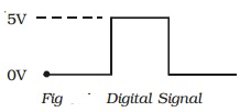
A digital signal (pulse) is shown in Fig. It has two discrete levels, ‘High’ and ‘Low’. In most cases, the more positive of the two levels is called HIGH and is also referred to as logic 1. The other level becomes low and also called logic 0. This method of using more positive voltage level as logic 1 is called a positive logic system.

A voltage 5V refers to logic 1 and 0 V refers to logic 0. On the other hand, in a negative logic system, the more negative of the two discrete levels is taken as logic 1 and the other level as logic 0. Both positive and negative logic are used in digital systems. But, positive logic is more common of logic gates. Hence we consider only positive logic for studying the operation of logic gates.

