Series resonance or voltage resonance in RLC circuit:
The value of current at any instant in a series RLC circuit is given by

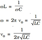
At a particular value of the angular frequency, the inductive reactance and the capacitive reactance will be equal to each other (i.e.)
![]()
So that the impedance becomes minimum and it is given by Z = R.
i.e. I is in phase with V
The particular frequency ν0 at which the impedance of the circuit becomes minimum and therefore the current becomes maximum is called resonant frequency of the circuit. Such a circuit which admits maximum current is called series resonant circuit or acceptor circuit. Thus the maximum current through the circuit at resonance is
![]()
Maximum current flows through the circuit, since the impedance of the circuit is merely equal to the ohmic resistance of the circuit. i.e Z = R

Acceptor circuit:
The series resonant circuit is often called an ‘acceptor’ circuit. By offering minimum impedance to current at the resonant frequency it is able to select or accept most readily this particular frequency among many frequencies.
In radio receivers, the resonant frequency of the circuit is tuned to the frequency of the signal desired to be detected. This is usually done by varying the capacitance of a capacitor.
Q-factor
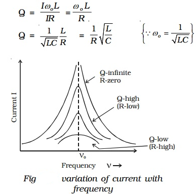
The selectivity or sharpness of a resonant circuit is measured by the quality factor or Q factor. In other words, it refers to the sharpness of tuning at resonance. The Q factor of a series resonant circuit is defined as the ratio of the voltage across a coil or capacitor to the applied voltage.

where ω0 is the angular frequency of the a.c. at resonance.
The applied voltage at resonance is the potential drop across R, because the potential drop across L is equal to the drop across C and they are 1800 out of phase. Therefore they cancel out and only potential drop across R will exist.

Q is just a number having values between 10 to 100 for normal frequencies. Circuit with high Q values would respond to a very narrow frequency range and vice versa. Thus a circuit with a high Q value is sharply tuned while one with a low Q has a flat resonance. Q-factor can be increased by having a coil of large inductance but of small ohmic resistance.
Current frequency curve is quite flat for large values of resistance and becomes more sharp as the value of resistance decreases. The curve shown in Fig is also called the frequency response curve.

