

Junction Diode as a rectifier
The process in which alternating voltage or alternating current is converted into a direct voltage or direct current is known as rectification. The device used for this process is called as a rectifier. The junction diode has the property of offering low resistance and allowing current to flow through it, in the forward biased condition. This property is used in the process of rectification.
Half wave rectifier:
A circuit which rectifies half of the a.c wave is called half wave rectifier.
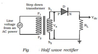
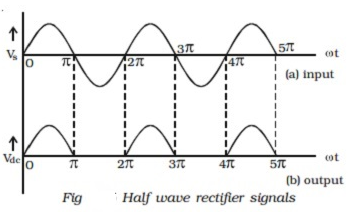
Fig shows the circuit for half wave rectification. The a.c. voltage (Vs) to be rectified is obtained across the secondary ends S1 S2 of the transformer. The P-end of the diode D is connected to S1 of the secondary coil of the transformer. The N-end of the diode is connected to the other end S2 of the secondary coil of the transformer, through a load resistance RL. The rectified output voltage Vdc appears across the load resistance RL.
During the positive half cycle of the input a.c. voltage Vs, S1 will be positive and the diode is forward biased and hence it conducts. Therefore, current flows through the circuit and there is a voltage drop across RL. This gives the output voltage as shown in Fig.
During the negative half cycle of the input a.c. voltage (Vs), S1 will be negative and the diode D is reverse biased. Hence the diode does not conduct. No current flows through the circuit and the voltage drop across RL will be zero. Hence no output voltage is obtained. Thus corresponding to an alternating input signal, the unidirectional pulsating output is obtained.
The ratio of d.c. power output to the a.c. power input is known as rectifier efficiency. The efficiency of half wave rectifier is approximately 40.6%.
Bridge rectifier:
A bridge rectifier is shown in Fig. There are four diodes D1, D2, D3 and D4 used in the circuit, which are connected to form a network. The input ends A and C of the network are connected to the secondary ends S1 and S2 of the transformer. The output ends B and D are connected to the load resistance RL.
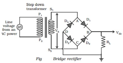
- During positive input half cycle of the a.c. voltage, the point A is positive with respect to C.
- The diodes D1 and D3 are forward biased and conduct, whereas the diodes D2 and D4 are reverse biased and do not conduct. Hence current flows along S1ABDCS2 through RL.
- During the negative half cycle, the point C is positive with respect to A.
- The diodes D2 and D4 are forward biased and conduct; whereas the diodes D 1 and D3 are reverse biased and they do not conduct. Hence current flows along S2CBDAS 1 through RL.
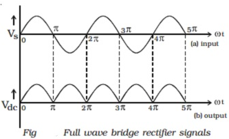
- The same process is repeated for subsequent half cycles. It can be seen that current flows through RL in the same direction, during both half cycles of the input a.c. signals.
- The output signal corresponding to the input signal is shown in Fig. The efficiency of the bridge rectifier is approximately 81.2%.