
Amplitude Modulation
In amplitude modulation, the amplitude of the carrier is varied in accordance with the information signal.
AM can be represented by expression
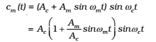
Let c(t) = Ac sinωct represent carrier wave and m(t) = Am sint represent the message or the modulating signal where m = 2fm is the angular frequency of the message signal. The modulated signal cm (t) can be written as
![]()
Here μ = Am/Ac is the modulation index; in practice, μ is kept ≤ 1 to avoid distortion.
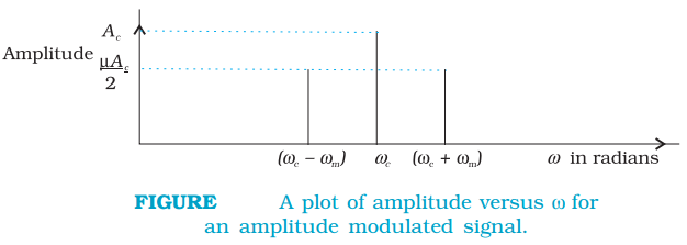
Using the trigonometric relation sinA sinB = ½ (cos(A – B) – cos (A + B), we can write cm(t)
![]()
Here ωc – ωm and ωc + ωm are respectively called the lower side and upper side frequencies. The modulated signal now consists of the carrier wave of frequency ωc plus two sinusoidal waves each with a frequency slightly different from, known as side bands. The frequency spectrum of the amplitude modulated signal is shown in Fig.
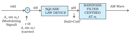
Production of AM Wave: One of the simplest methods is shown below by block diagram.
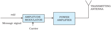
It is to be mentioned that the modulated signal cannot be transmitted as such. The modulator is to be followed by a power amplifier which provides the necessary power and then the modulated signal is fed to an antenna of appropriate size for radiation as shown in Fig.
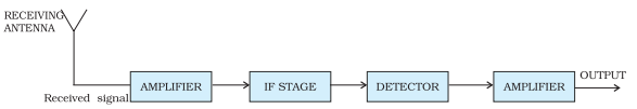
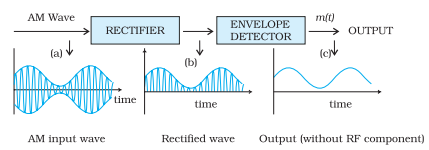
The transmitted message gets attenuated in propagating through the channel. The receiving antenna is, therefore, to be followed by an amplifier and a detector. In addition, to facilitate further processing, the carrier frequency is usually changed to a lower frequency by what is called an intermediate frequency (IF) stage preceding the detection. Detection is the process of recovering the modulating signal from the modulated carrier wave.