Let an alternating source of emf e be connected to a series combination of a resistor of resistance R, an inductor of inductance L and a capacitor of capacitance C (fig. a).

Let the current flowing through the circuit be I.
The voltage drop across the resistor is, VR = I R (This is in phase with I)
The voltage across the inductor coil is VL = I XL (VL leads I by π/2)
The voltage across the capacitor is, VC = IXC (VC lags behind I by π/2)
The voltages across the different components are represented in the voltage phases diagram (Fig. b).
VL and VC are 1800 out of phase with each other and the resultant of VL and VC is (VL – VC), assuming the circuit to be predominantly inductive. The applied voltage ‘V’ equals the vector sum of VR, VL and VC.

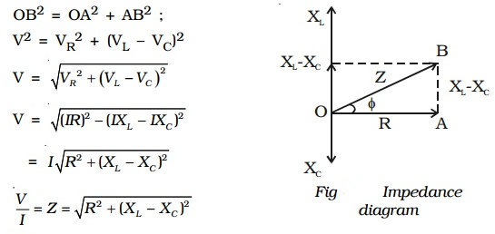
The expression is the net effective opposition offered by the combination of resistor, inductor and capacitor known as the impedance of the circuit and is represented by Z. its unit is ohm. The values are represented in the impedance diagram (Impedance diagram)
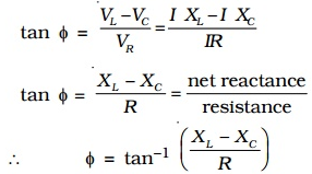
Phase angle ϕ between the voltage and current is given by

∴ is the instantaneous current flowing in the circuit.

