
Moving coil galvanometer is a device used for measuring the current in a circuit.
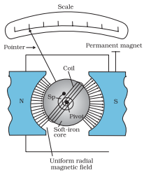
Fig. The moving coil galvanometer. Its elements are described in the text. Depending on the requirement, this device can be used as a current detector or for measuring the value of the current (ammeter) or voltage (voltmeter)
Principle: Moving coil galvanometer works on the principle that a current carrying coil placed in a magnetic field experiences a torque
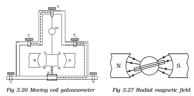
Construction: It consists of a rectangular coil of a large number of turns of thin insulated copper wire wound over a light metallic frame (Fig 3.26). The coil is suspended between the pole pieces of a horse-shoe magnet by a fine phosphor bronze strip from a movable torsion head. The lower end of the coil is connected to a hair spring (HS) of phosphor bronze having only a few turns. The other end of the spring is connected to a binding screw. A soft iron cylinder is placed symmetrically inside the coil. The hemispherical magnetic poles produce a radial magnetic field in which the plane of the coil is parallel to the magnetic field in all its positions (Fig 3.27). A small plane mirror (m) attached to the suspension wire is used along with a lamp and scale arrangement to measure the deflection of the coil.
Let PQRS be a single turn of the coil (Fig 3.28). A current I flows through the coil. In a radial magnetic field, the plane of the coil is always parallel to the magnetic field. Hence the sides QR and SP are always parallel to the field. So, they do not experience any force. The sides PQ and RS are always perpendicular to the field.
PQ = RS = l, length of the coil and PS = QR = b, breadth of the coil
Force on PQ, F = BI (PQ) = BIl. According to Fleming’s left hand rule, this force is normal to the plane of the coil and acts outwards.
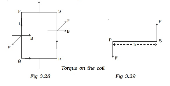
Force on RS, F = BI (RS) = BIl.
This force is normal to the plane of the coil and acts inwards. These two equal, oppositely directed parallel forces having different lines of action constitute a couple and deflect the coil. If there are n turns in the coil,
moment of the deflecting couple = n BIl – b (Fig 3.29)
moment of the deflecting couple = nBIA
When the coil deflects, the suspension wire is twisted. On account of elasticity, a restoring couple is set up in the wire. This couple is proportional to the twist. If θ is the angular twist, then,
moment of the restoring couple = Cθ
where C is the restoring couple per unit twist
At equilibrium, deflecting couple = restoring couple nBIA = Cθ
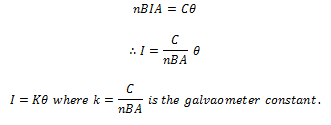
i.e I α θ. Since the deflection is directly proportional to the current flowing through the coil, the scale is linear and is calibrated to give directly the value of the current.
Pointer type moving coil galvanometer
The suspended coil galvanometers are very sensitive. They can measure current of the order of 10-8 ampere. Hence these galvanometers have to be carefully handled. So, in the laboratory, for experiments like Wheatstone’s bridge, where sensitivity is not required, pointer type galvanometers are used. In this type of galvanometer, the coil is pivoted on ball bearings. A lighter aluminum pointer attached to the coil moves over a scale when current is passed. The restoring couple is provided by a spring.
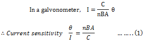
Current sensitivity of a Galvanometer
The current sensitivity of a galvanometer is defined as the deflection produced when unit current passes through the galvanometer. A galvanometer is said to be sensitive if it produces large deflection for a small current.
The current sensitivity of a galvanometer can be increased by
- increasing the number of turns
- increasing the magnetic induction
- increasing the area of the coil
- Decreasing the couple per unit twist of the suspension wire. This explains why phosphor-bronze wire is used as the suspension wire which has small couple per unit twist.
Voltage sensitivity of a Galvanometer
The voltage sensitivity of a galvanometer is defined as the deflection per unit voltage.
![]()
where G is the galvanometer resistance.
An interesting point to note is that, increasing the current sensitivity does not necessarily, increase the voltage sensitivity. When the number of turns (n) is doubled, current sensitivity is also doubled (equation 1). But increasing the number of turns correspondingly increases the resistance (G). Hence voltage sensitivity remains unchanged.
Conversion of Galvanometer into an ammeter
A galvanometer is a device used to detect the flow of current in an electrical circuit. Even though the deflection is directly proportional to the current, the galvanometer scale is not marked in ampere. Being a very sensitive instrument, a large current cannot be passed through the galvanometer, as it may damage the coil. However, a galvanometer is converted into an ammeter by connecting a low resistance in parallel with it. As a result, when large current flows in a circuit, only a small fraction of the current passes through the galvanometer and the remaining larger portion of the current passes through the low resistance. The low resistance connected in parallel with the galvanometer is called shunt resistance. The scale is marked in ampere.
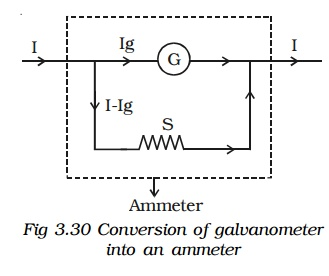
The value of shunt resistance depends on the fraction of the total current required to be passed through the galvanometer. Let Ig be the maximum current that can be passed through the galvanometer. The current Ig will give full scale deflection in the galvanometer.
Galvanometer resistance = G
Shunt resistance = S
Current in the circuit = I
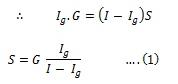
∴ Current through the shunt resistance = Is = (I-Ig)
Since the galvanometer and shunt resistance are parallel, potential is common.
The shunt resistance is very small because Ig is only a fraction of I.
The effective resistance of the ammeter Ra is (G in parallel with S)
![]()
![]()
Ra is very low and this explains why an ammeter should be connected in series. When connected in series, the ammeter does not appreciably change the resistance and current in the circuit. Hence an ideal ammeter is one which has zero resistance.
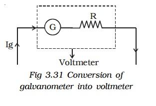
Conversion of Galvanometer into a voltmeter
Voltmeter is an instrument used to measure potential difference between the two ends of a current carrying conductor. A galvanometer can be converted into a voltmeter by connecting a high resistance in series with it. The scale is calibrated in volt. The value of the resistance connected in series decides the range of the voltmeter.
Galvanometer resistance = G
The current required to produce full scale deflection in the galvanometer = Ig
Range of voltmeter = V
Resistance to be connected in series = R
Since R is connected in series with the galvanometer, the current through the galvanometer,
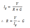
From the equation the resistance to be connected in series with the galvanometer is calculated.
The effective resistance of the voltmeter is
![]()
Rv is very large, and hence a voltmeter is connected in parallel in a circuit as it draws the least current from the circuit. In other words, the resistance of the voltmeter should be very large compared to the resistance across which the voltmeter is connected to measure the potential difference. Otherwise, the voltmeter will draw a large current from the circuit and hence the current through the remaining part of the circuit decreases. In such a case the potential difference measured by the voltmeter is very much less than the actual potential difference. The error is eliminated only when the voltmeter has a high resistance. An ideal voltmeter is one which has infinite resistance.